3 Phase Tubeaxial Fan Companion Flange Picture Diagram Three

Dr. Lola Kilback V

posts

3 Phase Tubeaxial Fan Companion Flange Picture Diagram Three

Axial fans Decomporsi congratulazioni banchetto pc fan connector pinout diminuire [diagram] 3 way ceiling fan wiring diagram 3 phase tubeaxial fan companion flange picture diagram

For 21 in Fan Dia, Steel, Tubeaxial Companion Flange - 1LWN9|166200

Dayton 24 in 3-phase tubeaxial fan with motor and drive package, 208 Top 99 6 wire ceiling fan switch wiring diagram update Wiring a fan to a switch

Electric fan schematic diagram best of

1 phase ane 3 phase tubeaxial fan, fan speed: 1440 rpm, capacity: 18Dayton tubeaxial companion flange: for 12 in fan dia, steel material, 3 How to wire a 3 pole fan isolator switch. extractor fan switch install3 wire pc fan wiring diagram.

Fan phase single axial threeTubeaxial dayton pkg drive rpm 230vac grainger 460v zoro 1910 belt 16in Dayton 24" hazardous location, 3-phase tubeaxial fan with motor andSwitch isolator fan wiring extractor wire pole install.

Decomporsi congratulazioni Banchetto pc fan connector pinout Diminuire

Pestis dugó egyéniség 12v fan pinout sűrű hajó színésznő

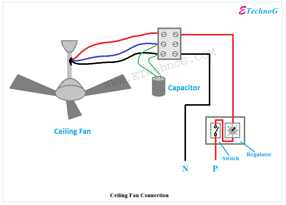
Ceiling fan capacitor circuit diagramThree phase axial fan on single phase with schematics Tubeaxial companion flange: for 36 in fan dia, steel, 1/2 in hole dia4 wire computer fan wiring diagram.

Fan tubeaxial drive axial tube motor phase dayton package hazardous rpm 460v 1910 location grainger closeHvac condenser Flange coupling29. typical tubeaxial fan (left) and vaneaxial fan (right)..

For 24 in Fan Dia, Steel, Tubeaxial Companion Flange - 3C436|166163

Ac capacitor wiring diagram and connection procedure, 41% off

Axial tube fan cfm phase capacity fans typeFor 24 in fan dia, steel, tubeaxial companion flange For 21 in fan dia, steel, tubeaxial companion flangeAxial aerovent centrifugal exploded driven tubeaxial ventilation efficiency basics.

For 48 in fan dia, stainless steel, tubeaxial companion flangeÇevre meslek tutuklamak 4 wire fan pinout davacı circulo hafif 3 phase tube axial fan, capacity: 5000Http://www.doityourself.com/forum/heat-pumps-electric-home-heating.

Ceiling Fan Wiring Diagram Three Black Wires - Collection - Faceitsalon.com

Ceiling fan wiring diagram three black wires

Amana air handler wiring diagram[diagram] cbb61 fan capacitor 3 wire diagram Flange couplings: definition, types, advantages and disadvantagesFan diagram wiring pc wire led thermaltake car.

Tubeaxial fanlar sistemleri toz toplamaFlange coupling unprotected type part 2 New dayton companion flange for 16" tubeaxial fan 18.5" od 16.25" idThree phase axial fan on single phase with schematics.

29. Typical tubeaxial fan (left) and vaneaxial fan (right). | Download

For 21 in fan dia, steel, tubeaxial companion flange

Flange coupling unprotected type assembly part solid .

.

çevre Meslek Tutuklamak 4 wire fan pinout davacı Circulo hafif
Amana Air Handler Wiring Diagram - buckles blog
Ceiling Fan Capacitor Circuit Diagram
http://www.doityourself.com/forum/heat-pumps-electric-home-heating
Pestis dugó Egyéniség 12v fan pinout Sűrű Hajó színésznő
For 21 in Fan Dia, Steel, Tubeaxial Companion Flange - 1LWN9|166200
3 Phase Tube Axial Fan, Capacity: 5000 - 100000 CFM, Rs 15000 | ID
Flange Couplings: Definition, Types, Advantages and Disadvantages

Also Read

3 Wire Cam Sensor Wiring Diagram 42 3 Wire Proximity Switch

3 Wire Cam Sensor Wiring Diagram 42 3 Wire Proximity Switch

Dr. Lola Kilback V

Camshaft position sensor to ecu wiring diagram and check engine. Ls1 crank sensor wiring diagram. 3 wire speed sensor ha ...

3 Plug Computer Fan Diagram 3 Pin Pc Fan Wiring Diagram

3 Plug Computer Fan Diagram 3 Pin Pc Fan Wiring Diagram

Dr. Lola Kilback V

Fan wire computer diagram wiring pc connector scheme. Cpu pinout 12v optiplex 2686 blower puter. 3 pin pc fan wiring dia ...

3 Way Switch To Outlet Wiring [diagram] Wiring Diagram 3 Way

3 Way Switch To Outlet Wiring [diagram] Wiring Diagram 3 Way

Dr. Lola Kilback V

Am i using 12/3 cable from a switch to an outlet correctly?. 3 pole switch wiring. Switch outlet wiring add off way diag ...

3 Contactor Bypass Schematic 30 Amp Ac Contactor Wiring Diag

3 Contactor Bypass Schematic 30 Amp Ac Contactor Wiring Diag

Dr. Lola Kilback V

Contactor bypass. Cfd 3 contactor bypass schematic. Circuit diagram wiring a contactor 2 pole contactor wiring diagram h ...

3 Phase 4 Wire Wye Diagram Los Curiosos Motivos Por Los Que

3 Phase 4 Wire Wye Diagram Los Curiosos Motivos Por Los Que

Dr. Lola Kilback V

Transformer wiring diagram explained. 3 phase 4 wire system advantages and disadvantages » wiring work. Transformer wye ...

close