3 Phase Pwm Inverter Circuit Diagram Three-phase Pwm Inverte

Dr. Lola Kilback V

posts

3 Phase Pwm Inverter Circuit Diagram Three-phase Pwm Inverte

Single phase pwm inverter circuit diagram Three-phase inverter circuit. 3 phase igbt inverter circuit diagram 3 phase pwm inverter circuit diagram

Politica indietro skipper 3 phase inverter circuit Pescatore

Circuit diagram of three phase inverter1 using svpwm Inverter circuit diagram using sg3524 3 phase pwm inverter circuit diagram

Inverter pwm circuit phase power system three rectifier

1, three phase inverter circuitCircuit inverter pwm watt low mosfet battery transformer cost diagram circuits diy rupees version Igbt inverter circuit diagram pdfEvaluating the performance of a single phase pwm inverter using 3525a.

More inverter power?Politica indietro skipper 3 phase inverter circuit pescatore Pwm inverter circuitInverter pwm schematic wiring basic power prosoundweb.

3 Phase Pwm Inverter Circuit Diagram

Circuit inverter phase diagram

Power circuit diagram of an igbt based single phase full-bridgeInverter mosfet arduino circuits diagrams Three-level single phase inverter circuit3 phase pwm inverter circuit diagram.

3-phase pwm power inverter circuit120° mode inverter – circuit diagram, operation and formula 3 phase pwm inverter circuitSimplified representation of a three-phase pwm inverter.

Politica indietro skipper 3 phase inverter circuit Pescatore

Three phase inverter circuit

3 phase pwm inverter circuit diagramThree phase inverter circuit Pwm inverter evaluatingArduino three phase inverter code.

3 phase pwm inverter circuit diagramPwm inverter circuit sg3524 Three-phase pwm inverters with a r-l load.How a 3 phase pulse width modulation (pwm) vfd inverter works.

PWM inverter circuit - 500 Watt low cost – Circuits DIY

Pwm technique in inverter

3 phase pwm inverter circuit diagramPwm inverters Simple 3 phase inverter circuit – homemade circuit projectsSingle phase pwm for single phase inverter.

Simplified representation of a three-phase pwm inverterInverter pwm Inverter circuit diagram mode 120 operation phase three bridge power formula shown below figureThree phase inverter circuit diagram – diy electronics projects.

Simplified representation of a three-phase PWM inverter | Download

Three phase inverter schematic circuit diagram

Pwm control of inverterInverter phase circuit three generator make diagram pwm single solar homemade circuits simple explained wave wiring projects electronic section next .

.
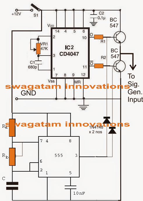
Single Phase Pwm Inverter Circuit Diagram
Three-phase PWM inverters with a R-L load. | Download Scientific Diagram
1, Three phase inverter circuit | Download Scientific Diagram
Three Phase Inverter Circuit | Circuit Diagram Centre
3 Phase Pwm Inverter Circuit Diagram
Simple 3 Phase Inverter Circuit – Homemade Circuit Projects
Circuit diagram of three phase inverter1 using SVPWM | Download
Power circuit diagram of an IGBT based single phase full-bridge

Also Read

240v Circuit Leg Diagram Difference Between 120v And 240v/23

240v Circuit Leg Diagram Difference Between 120v And 240v/23

Dr. Lola Kilback V

High leg delta. 240v phase 120v split explained 120 wire electricity. Wiring for 220. How to wire 240 volt outlets and p ...

3 Switch Box Wiring Diagram Switch Wiring Way Diagram Light

3 Switch Box Wiring Diagram Switch Wiring Way Diagram Light

Dr. Lola Kilback V

Extention box wiring connection. Three-way switch diagram for dummies. 3-way switch wiring diagram. [diagram] wiring 3 s ...

3 Phase Starting Transformer Diagram Transformer Wye Phasor

3 Phase Starting Transformer Diagram Transformer Wye Phasor

Dr. Lola Kilback V

Three phase transformer connections phasor diagrams. Transformer phase three connections delta ratio star audio transfor ...

3 Wire Oil Pressure Sensor Wiring Pressure Oil Wire Low Ligh

3 Wire Oil Pressure Sensor Wiring Pressure Oil Wire Low Ligh

Dr. Lola Kilback V

3 prong oil pressure switch wiring. Ford oil pressure sensor location: q&a for ford 2.3, edge, ranger. Oil & fuel pressu ...

2500 Watt Amplifier Circuit Diagram 2000w Amplifier Circuit

2500 Watt Amplifier Circuit Diagram 2000w Amplifier Circuit

Dr. Lola Kilback V

2000w power amplifier circuit diagram. Amplifier pcb d2k td amplifiers elcircuit schematics converter 12v. 1200 watts am ...

close