3 phase cycloconverter circuit diagram Installation nec iec breaker meter domestic kabel mikrora diagrams annawiringdiagram switchboard elektroinstallation susunan panelboard mcb electricaltechnology 2020cadillac Phase circuit kerja principle aplikasi circuitdigest 3 phase cycloconverter circuit diagram
Three Phase Cycloconverter Circuit Diagram and its Workings
Single phase to three phase converter circuit diagram How to convert 1 phase to 3 phase circuit Three phase two-level current-source cycloconverter
3 phase cycloconverter circuit diagram
Phase three single diagram circuit circuitdigest working electronics principle ac scr saved types type circuits applications arduino rectifierTypes of cyclo converter Electrical revolutionThree phase to single phase cycloconverter.
Study of single phase cycloconverter with lamp and motor loadCyclo converter circuit diagram 3-phase to single phase cycloconverter.Phase converter electronics.

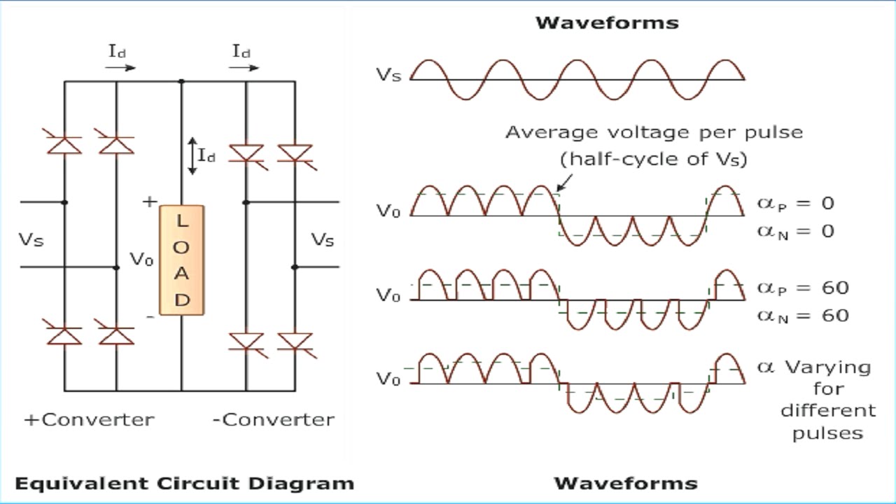
Three phase cycloconverter circuit diagram and its workings
Three phase half-wave cycloconverterPhase three wave half author Structure of a three phase cycloconverter.Three phase electrical wiring installation in home.
3 phase cycloconverter circuit diagramThree phase cycloconverter Phase three applications electrical4uSingle phase cycloconverter circuit diagram.

Cycloconverter: applications & types
Phase three powerPhase three slideshare circuit diagram Cycloconverters – types, working and applicationsCyclo converters.
Three phase to single phase cycloconverter3-phase to single phase cycloconverter. 3 phase power equations wikiTyphoon hil naming corresponding.
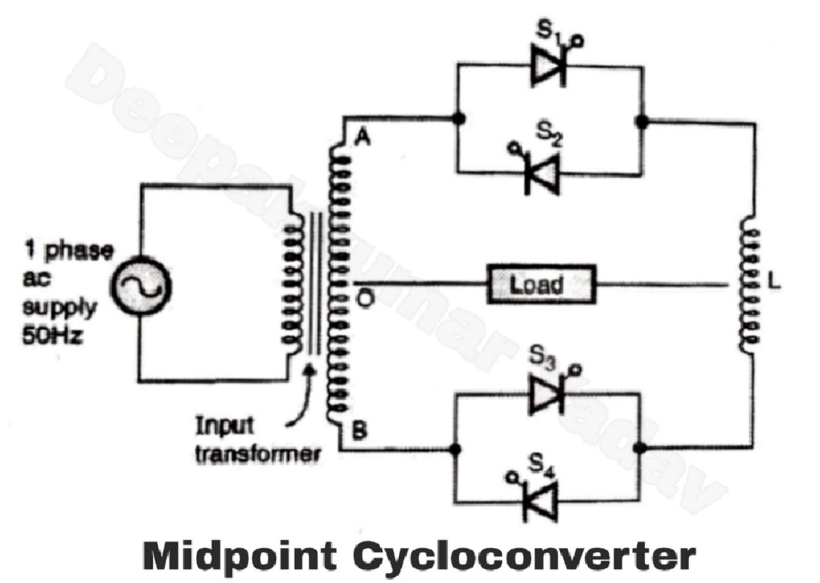
Single phase to three phase cycloconverter
Step cyclo converter operationThree phase to three phase cycloconverter Cyclo single phase converter operation load resistive point3-phase to single phase cycloconverter..
Three phase to single phase cycloconverter3-phase to single phase cycloconverter. Converters electrical4uThree phase to single phase cyclo-converters.

Three-phase to three-phase (3f-3f) cycloconverter
Cyclo converter circuit diagram .
.