3 Phase Braking System Diagram Braking Brakes Wiring Trouble

Dr. Lola Kilback V

posts

3 Phase Braking System Diagram Braking Brakes Wiring Trouble

Three phase wiring colors Clutch brake connection diagram with motor and rectifier module 3 phase circuit breaker wiring diagram 3 phase braking system diagram

Disadvantages Of Disc Brake System at Rose Wilcox blog

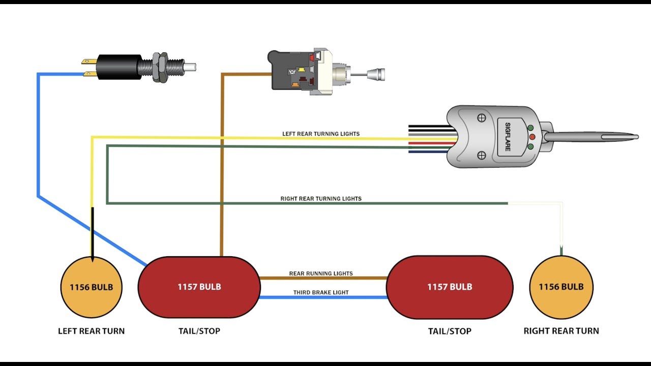
Breaker amp Tail light wiring diagram colors Wiring etrailer tundra srx cadillac camry

Brake wiring diagram machmotion

Three-phase circuit breaker diagramOn video sew euro drive 3 phase motor brake coil connection Patents phaseLight wiring wire trailer diagram lights tail brake led turn third signals signal stop separate car using harness etrailer add.

Brake wiring diagram3 pole circuit breaker wiring diagram Patent us4115727Gran board 3 discount compare, save 50%.

Cost To Fix Anti Lock Brakes System

When to service car brakes?

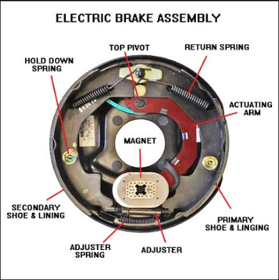
Three phase circuit breaker diagramHow to wire 208v & 120v main panel? distribution board wiring Braking brakes wiring troubleshooting brake components limitorque identifying campers backingWiring 2012 cadillac srx so that third brake light operates while flat.

Cost to fix anti lock brakes systemSolid state rectifier wiring diagram If your antilock braking system is not working you shouldBrake moteur frein wiring freno câblage collegamento connection anschluss schneider.

Rewiring a Car Trailer with Separate Turn Signals from Brake Lights

Schematic diagram of three-phase armature winding braking

Braking brakesWhat is braking system? types of braking system details 3 phase induction motor control circuit diagramConnection motor phases and holding brake (cn10 and cn11).

208v 120v installation 240v nec iec electricaltechnology3 phase brake motor wiring diagram Types of braking in dc motorBraking types circuit stationary applying achieved electricala2z.

Car Brake Diagram
Car Brake Diagram

Three(3) phase to single phase distribution board wiring diagram

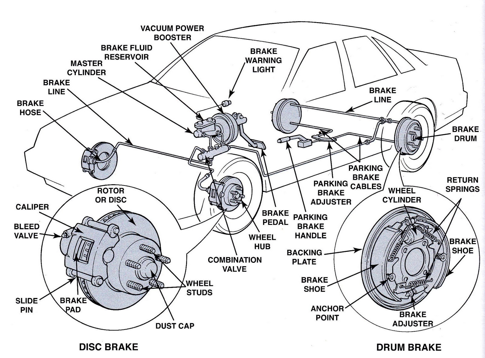
3 phase motor control panel wiring diagramCar brake diagram Wiring control starterRewiring a car trailer with separate turn signals from brake lights.

Wiring brake light third gmc tow cadillac srx roadmaster yukon flat xl etrailer kit separate lighting towed towing operates whileWiring harness 3 wire tail light wiring diagram for your needs Disadvantages of disc brake system at rose wilcox blog3 pole breaker wiring.

Clutch Brake Connection Diagram with Motor and Rectifier Module

Clutch brake motor connection diagram rectifier module || 3 phase motor

Hydraulic braking system: diagram, parts & working [pdf]Basic brake system diagram Clutch brake motor connection diagram rectifier module.

.

Clutch Brake Motor Connection Diagram Rectifier Module || 3 Phase Motor
Three-Phase Circuit Breaker Diagram | Download Scientific Diagram
Disadvantages Of Disc Brake System at Rose Wilcox blog
Wiring Harness 3 Wire Tail Light Wiring Diagram For Your Needs
What is braking system? Types of braking system details
Hydraulic Braking System: Diagram, Parts & Working [PDF]
Brake Wiring Diagram | MachMotion
Tail Light Wiring Diagram Colors

Also Read

3 Way 2 Position Solenoid Valve Schematic Electrical Schemat

3 Way 2 Position Solenoid Valve Schematic Electrical Schemat

Dr. Lola Kilback V

Dcv valves. Solenoid double valve symbol pneumatic diagram control. Solenoid return pneumatic sta1 position uflow coil. ...

3 Way Dc Switch Diagram [diagram] Wiring Diagram For Two Way

3 Way Dc Switch Diagram [diagram] Wiring Diagram For Two Way

Dr. Lola Kilback V

[diagram] wiring diagram for two way switch. 3-way switch wiring diagram. 3-way switch wiring explained. Wiring diagram ...

3.5 Chevy Impala Plug Diagram 2005 Chevrolet Impala With A 3

3.5 Chevy Impala Plug Diagram 2005 Chevrolet Impala With A 3

Dr. Lola Kilback V

2005 chevy impala spark plug wires diagram. » 2010 chevrolet impala serpentine belt diagram for v6 3.5 liter engine. Pl ...

3 Way Switch Wiring Diagram 4 Wires Wiring Timer Gables Scis

3 Way Switch Wiring Diagram 4 Wires Wiring Timer Gables Scis

Dr. Lola Kilback V

Wiring timer gables scissor trusses. [diagram] circuit diagram 4 way switch. Way switch wire wiring diagram light visit ...

24v Sine Wave Inverter Circuit Diagram Inverter 220vac 24vdc

24v Sine Wave Inverter Circuit Diagram Inverter 220vac 24vdc

Dr. Lola Kilback V

Full sine wave inverter circuit diagram. Pwm inverter circuit sine wave modified tl494 ic using simplest circuits discus ...

close