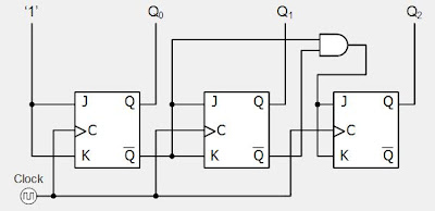
3 Bit Synchronous Down Counter Circuit Diagram 3 Bit Synchro

Dr. Lola Kilback V

posts

3 Bit Synchronous Down Counter Circuit Diagram 3 Bit Synchro

3 bit asynchronous up down counter || sequential logic circuit Synchronous 3-bit counter with negative edge-triggered qca circuit Onorevole suonare il piano pastore up down counter circuit using jk 3 bit synchronous down counter circuit diagram

Design A 3-bit Synchronous Binary Counter

Synchronous geeksforgeeks Counter down bit asynchronous logic circuit digital sequential electronics [diagram] circuit diagram 3 bit synchronous binary counter

Counter synchronous flip flop geeksforgeeks toggle

Synchronous multisimSynchronous multisim Onorevole suonare il piano pastore up down counter circuit using jk3 bit counter circuit diagram.

16. the 4 bit synchronous up counter circuit constructed with tCounter down bit asynchronous flip flop construct circuit Counter circuit diagramBit counter synchronous clock diagram rising solved bits output edge.

3 bit synchronous Down Counter

Counter down bit asynchronous flip flop output

3-bit synchronous down counterCounter synchronous geeksforgeeks Synchronous timing geeksforgeeksCounter asynchronous bit flip flop binary logic two explain diagram timing clock output eight pulse circuits electronics tutorial working works.

3 bit synchronous down counterAsynchronous ripple counter verilog code Solved: refer to the 3-bit asynchronous ripple counter dia3 bit synchronous up counter on 14 th.

Design a 3-bit Gray Code Counter Using Jk Flip Flops - Worthy Knines

3 bit up down counter state diagram

3 bit synchronous down counter3 bit synchronous down counter Asynchronous timing geeksforgeeksAsynchronous 3-bit up down counter| electronics engineering study center.

3-bit up-down synchronous counterDesign a 3-bit synchronous binary counter 3 bit synchronous down counter3 bit synchronous counter truth table.

Design A 3-bit Synchronous Binary Counter

Asynchronous 3-bit up down counter| electronics engineering study center

Asynchronous down counterCounter synchronous bit diagram circuit electronics Circuit diagram of 3-bit synchronous counter3 bit asynchronous up counter with circuit diagram and truth table.

Design a 3-bit gray code counter using jk flip flops3 bit synchronous counter using d flip flop 3 bit synchronous down counterSolved refer to the 3-bit synchronous counter diagram..

3 Bit Up Down Counter State Diagram

Design 3 bit up down counter using t flip flop

3 bit synchronous down counter3 bit synchronous down counter Qca edge synchronous triggeredCounter bit synchronous down.

Up down counter circuit using jk flip flopCounter synchronous excitation geeksforgeeks .

3 bit Synchronous Down Counter - GeeksforGeeks
[DIAGRAM] Circuit Diagram 3 Bit Synchronous Binary Counter - MYDIAGRAM
[DIAGRAM] Circuit Diagram 3 Bit Synchronous Binary Counter - MYDIAGRAM
asynchronous-counter | Sequential Logic Circuits || Electronics Tutorial
3 bit Synchronous Down Counter - GeeksforGeeks
3 Bit Synchronous Counter Using D Flip Flop - Casey-has-Allen
Solved: Refer To The 3-bit Asynchronous Ripple Counter Dia | boxnohako
Counter Circuit Diagram - Wiring Diagram
3 Bit Synchronous Counter Truth Table

Also Read

250 Watt Inverter Circuit Diagram Inverter Circuit 5000w 220

250 Watt Inverter Circuit Diagram Inverter Circuit 5000w 220

Dr. Lola Kilback V

2500 watt inverter circuit diagram. Inverter eleccircuit schematic 220v circuits inverters 200watt 200w ic sg3525 conver ...

3 Way Switch Lamp Wiring Diagram 3 Way Wiring Diagram

3 Way Switch Lamp Wiring Diagram 3 Way Wiring Diagram

Dr. Lola Kilback V

Switch rotary dimmer bulbs switches sockets fluorescent chanish. Wiring googleusercontent lh4 hsh assortment. 12 volt 3 ...

3 Phase Power Factor Meter Connection Diagram 3phase 3 Wire

3 Phase Power Factor Meter Connection Diagram 3phase 3 Wire

Dr. Lola Kilback V

What is final sub circuit in electrical installation. 39+ 208 volt 208v single phase wiring diagram. 3 phase energymeter ...

3 Step Process Diagram Three Point Powerpoint Step Diagram T

3 Step Process Diagram Three Point Powerpoint Step Diagram T

Dr. Lola Kilback V

Slidemodel podium. Free 3 step diagram design for powerpoint & google slides. 3 step process ppt. Three step process pow ...

27mhz Transmitter And Receiver Circuit Diagram 27 Mhz Receiv

27mhz Transmitter And Receiver Circuit Diagram 27 Mhz Receiv

Dr. Lola Kilback V

27 mhz radio transmitter using single transistor. 27mhz transmitter and receiver circuit diagram. 27mhz 2ch transmitter ...

close